What Is a Layer 2 Network? - Data Link Layer Networking


A Layer 2 network operates at the Data Link Layer of the OSI model and is responsible for node-to-node data transfer and error detection. It uses switching and bridging technologies to facilitate communication within a local area network (LAN). Layer 2 networks are fundamental for creating LANs and are the basis for technologies such as Ethernet and Wi-Fi.
Layer 2 networks use MAC addresses to identify devices on the network and manage data frames, which are the units of data transmission. Key functions of layer 2 networks include frame synchronization, error checking, and flow control, ensuring that data is transferred accurately and efficiently between directly connected nodes.
Components of a layer 2 network
Frames
Frames are the fundamental units of data transmission in a layer 2 network. You can visualize them as envelopes containing data that must be sent from one place to another within a Local Area Network (LAN). The moment you send a file to a network printer or access a shared folder, frames come into play.
Frames consist of a header, payload, and trailer. The header contains crucial information such as the MAC addresses of the source and destination devices. For instance, if your computer wants to send a document to a printer connected to the same LAN, the frame will include your computer's MAC address as the source and the printer's MAC address as the destination. This ensures the data reaches the correct endpoint.
The payload is where the actual data resides. It’s like the content of the letter inside your envelope. It can contain various types of data, whether it's an email, a document, or a video stream.
Meanwhile, the trailer often includes error-checking mechanisms. For example, if you send a package with a fragile sticker, the trailer ensures your data hasn't been damaged during transmission by performing a Cyclic Redundancy Check (CRC).
Switches in a Layer 2 network play a crucial role in handling these frames. They maintain a MAC address table, which records which MAC addresses are reachable on which ports.
When a frame arrives, the switch reads the destination MAC address and forwards the frame to the appropriate port. For example, if you are sending a file to a colleague on the same network, the switch ensures it travels directly to their computer without unnecessary detours.
Broadcast frames are another interesting component. Sometimes, a device needs to communicate with all devices on the network. In such cases, the frame is sent to the broadcast address, usually FF:FF:FF:FF:FF:FF. When you first connect a device to the network and it needs an IP address through DHCP, it will send out a broadcast frame to find the DHCP server.
The practical impact of understanding and managing frames cannot be overstated, especially in a business environment. Proper frame handling ensures efficient data transmission and minimizes network congestion.
For instance, by setting up VLANs (Virtual Local Area Networks), you can segment a larger network into smaller, manageable pieces. Each VLAN behaves like its separate network, reducing unnecessary broadcast traffic and improving overall performance.
Frames are the unsung heroes of our Layer 2 network. They may seem small and insignificant, but without them, data would never find its way through the intricate maze of our company networks.
MAC addresses
A MAC (Media Access Control) address is a unique identifier assigned to a network interface card (NIC) by the manufacturer. Each device that connects to the network has its own MAC address, kind of like a digital fingerprint. So, MAC addresses can be described as the nuts and bolts of how devices identify and communicate on a local network.
For instance, if you have a laptop and a printer connected to the same network, each will have its own distinct MAC address. These addresses are typically written in hexadecimal format, like `00:1A:2B:3C:4D:5E`. The MAC address is burned into the hardware, making it unique to that device. This uniqueness is crucial for the network to properly route data to the correct destination.
Layer 2 of the OSI model focuses on the link layer, which is responsible for local network traffic. Here, MAC addresses play a key role. When your laptop wants to send data to the printer, it uses the printer's MAC address.
The data packet includes both the source MAC address (from your laptop) and the destination MAC address (the printer). Switches within the network use these MAC addresses to forward the data to the correct device.
We often configure switches to learn which MAC addresses are associated with which ports. For example, if your laptop is connected to port 1 and your printer to port 2, the switch keeps an internal table mapping these ports to their respective MAC addresses. When data comes in, the switch consults this table to efficiently route the traffic without unnecessary broadcasting.
MAC addresses aren't just for identifying devices; they also help in network security. We use MAC address filtering to control which devices can access the network. If you have a new device you want to connect to, you’ll need to add its MAC address to an allowed list on the router or switch. This way, unauthorized devices can't just hop on and start communicating.
There are also scenarios where devices might need to spoof a MAC address. Let's say a server needs to maintain network access after a hardware upgrade. You can configure the new NIC with the old MAC address, making the transition seamless for the network.
Understanding and managing MAC addresses, therefore, ensures smooth, secure communication between devices. Whether troubleshooting a connectivity issue or implementing security policies, it’s essential that you know how MAC addresses work.
Switches
Layer 2 switches are the backbone of local area networks (LANs). They manage, and directing data packets based purely on MAC addresses. This makes them perfect for environments where the speed of intra-network data transfer is crucial.
Layer 2 switches essentially serve as multiport bridges. They offer full-duplex transmission, meaning data can be sent and received simultaneously. This ensures speedy communication, whether it's unicast (one-to-one), multicast (one-to-several), or broadcast (one-to-all).
Another strength of Layer 2 switches is their use of hardware-based switching, which can handle large volumes of data within a single network segment. In practical terms, this means if your company relies on heavy file transfers or high-definition video conferencing within the office, a Layer 2 switch can handle the load without breaking a sweat.
Layer 2 switches use Address Resolution Protocol (ARP) tables to navigate the network. For example, let's say your IT team installs new workstations. The switch quickly learns and maps the MAC addresses of these new devices, ensuring immediate and efficient data delivery.
However, Layer 2 switches have a limitation; their lack of built-in security features. They are susceptible to attacks like ARP spoofing. To tackle this, network administrators often employ additional security measures like port security, which limits the number of MAC addresses that can be associated with a single switch port.
For a small to medium-sized office with relatively straightforward networking needs, Layer 2 switches offer a cost-effective, simple-to-configure solution. They are ideal for setups where high-speed data transfer within a single network segment is a priority, and complex routing isn't needed.
Network Interface Cards (NICs)
NICs aren't just physical hardware; they operate significantly at the data link layer of the OSI model. NICs have their own unique MAC addresses which are essential for identifying devices within a network. This functionality places NICs squarely in Layer 2.
NICs handle MAC addressing, meaning every NIC has a unique Media Access Control (MAC) address burnt into it. When data is transmitted, the NIC includes its MAC address in the data frame's header as the Source MAC Address. This action is quintessential to Layer 2, as it helps devices on the same network segment identify each other.
For example, think of your computer connected to a local network. The NIC in your machine uses its MAC address to communicate with the router. It sends out data frames that include both the source (your NIC’s MAC address) and the destination MAC address (the router's NIC). This way, your router knows where the data came from and where it needs to go next.
Moreover, when your NIC receives a data frame, it examines the destination MAC address to determine if the data is meant for your computer. If it matches, the NIC processes the frame; otherwise, it discards it. This decision-making process happens entirely at Layer 2.
Another practical example can be seen in network troubleshooting. If two devices can’t communicate, checking their MAC addresses and ensuring they are correct can often resolve issues. This is because misconfigured or duplicated MAC addresses can cause a myriad of network problems.
In addition to basic MAC addressing, NICs can support more advanced Layer 2 features, like VLAN tagging and frame checksums. VLAN tagging allows the NIC to manage traffic segmentation, an essential feature in larger networks to maintain efficiency and security. Frame checksums help in error detection, ensuring data integrity during transmission.
Therefore, while NICs do have physical components aligning them with Layer 1 (the wires and signals), their primary operational domain with MAC addressing and frame handling firmly places them in Layer 2.
Ethernet
Ethernet switches connect devices within the same network. These switches are smart — they learn which devices are on which ports and then use this information to forward data only to the necessary destinations. This is unlike a hub, which just sends data to all ports regardless.
For example, if you’re working on a document with a colleague, the data packets are sent directly between your computers without bothering everyone else on the network.
Ethernet setups usually revolve around the IEEE 802.3 standard. This standard defines how network devices should format and transmit data over the network. It’s what makes sure your emails, files, and videos can flow smoothly through your cables.
You can use twisted pair cables (like Cat5e and Cat6) because they're reliable and support high-speed data transfer. For instance, Cat6 cables support speeds up to 10 Gbps, which is more than enough for regular daily business operations.
You can also implement VLANs to segment the network for security and efficiency. VLANs allow us to keep different departments in their own network spaces, even if they’re using the same physical infrastructure.
Spanning Tree Protocol (STP) is another critical component you can employ to prevent loops in your Ethernet network. Network loops can cause serious issues, like broadcast storms, which can bring our entire network to a standstill.
STP helps by identifying and shutting down redundant paths until they’re needed. For example, if one path fails, STP will activate a backup path to keep the network running smoothly.
Using Power over Ethernet (PoE) is another trick you can use. It allows you to power devices like IP phones, wireless access points, and security cameras directly through the Ethernet cables. This simplifies your setup since you don’t need separate power supplies for these devices.
Layer 2 network protocols
Spanning Tree Protocol (STP)
In a typical Layer 2 Network you have a network with multiple switches connected in various ways. Without some sort of governing protocol, data packets could end up getting caught in loops.
STP’s job is to prevent those loops. It does this by creating a loop-free logical topology for Ethernet networks. It decides the best path for data to travel, and if multiple paths exist, it temporarily blocks the redundant ones. This is useful if a part of the network goes down. STP can unblock those redundant paths, ensuring that your network remains operational.
For example, let’s say you have three switches: Switch A, Switch B, and Switch C. Switch A connects to both Switch B and Switch C. Switch B also connects to Switch C.
If STP weren't there, a broadcast packet could circulate endlessly between these switches, causing a "broadcast storm." This could bring the network to its knees. But STP steps in, elects one of the switches as the root bridge, and blocks the less efficient paths.
We often see STP in action in larger networks. Let’s take a typical scenario where a company has departments spread out across multiple floors. Each floor has its own switch.
These switches are connected to each other for redundancy. If the link between the second and third floor fails, STP can quickly reroute the traffic through an alternate path, keeping the network stable and reliable.
STP operates using Bridge Protocol Data Units (BPDUs), which are packets that switches exchange to share information about their ports and paths. When a switch boots up, it assumes it’s the root bridge and sends out a BPDU. But when it receives a BPDU from another switch with a lower root bridge ID, it defers to that switch. This self-organizing feature makes STP pretty robust.
The real beauty of STP is in its simplicity and effectiveness. When everyone is busy working and collaborating, STP quietly does its job in the background, ensuring data flows smoothly without interruption. Therefore, implementing STP means peace of mind.
There are more advanced versions like Rapid Spanning Tree Protocol (RSTP) and Multiple Spanning Tree Protocol (MSTP) that offer faster convergence times and support multiple VLANs, respectively. But at its core, STP is about keeping things loop-free and efficient.
Link Aggregation Control Protocol (LACP)
LACP is handy when you need more bandwidth or redundancy between your switches. Using it can enhance the performance and reliability of your Layer 2 network.
For example, when you're running multiple cables between two switches. Instead of just using one and leaving the others as backups, LACP lets you bundle those cables together into a single logical link. This way, you get to use all the cables at once, which boosts your bandwidth and gives us a lot of flexibility.
Say you have four 1Gbps links between two switches. Normally you’d use only one and keep the others as failovers. But with LACP, you can combine all four links into a single 4Gbps link. Pretty convenient, right? This setup not only increases speed but also provides redundancy. If one link fails, the data will just flow through the remaining links without a hitch.
LACP is quite versatile, too. It can dynamically adjust the number of active links in the aggregate, which means it can adapt if one of the links fails or comes back online. The protocol essentially balances the load across all active links, which optimizes the network traffic flow.
Another convenient attribute of LACP is that it’s standardized. It's part of the IEEE 802.3ad specification. This means it works across different vendors’ equipment, making your lives easier when managing a multi-vendor environment. So, if you have a Cisco switch on one end and an HP switch on the other, they can still talk LACP and create a link aggregation group.
When to use a layer 2 network
Layer 2 switching is great for smaller networks. It’s relatively easy to set up, requiring minimal configuration. For a small to medium-sized business, this simplicity can be a significant advantage.
Think about a startup setting up its first office. Connecting computers, phones, and printers with a layer 2 switch can be done quickly, ensuring everyone has the connectivity they need to get started.
Additionally, layer 2 switches are cost-effective, making them a good fit for organizations with budget constraints. You don’t need to invest in expensive hardware when a layer 2 switch can effectively handle the job. For example, a local retail store with a small number of connected devices would benefit from using layer 2 switches to manage its in-store network.
However, when your network grows and becomes more complex, requiring routing between different network segments or VLANs, you must consider the capabilities of a layer 3 switch. But, for many simpler needs, a dependable layer 2 switch is just the right tool for maintaining robust internal communications.
Switching modes for Layer 2 networks - Cut-through vs. Store-and-Forward
There are two main switching modes for the Layer 2 network: Store-and-Forward and Cut-Through. Understanding the difference between these is crucial for optimizing your network performance.
In Store-and-Forward mode, the switch receives the entire Ethernet frame before making any decisions. This is similar to reading the whole letter before deciding to whom it should be delivered.
This method ensures data integrity because the switch checks the frame's CRC (Cyclic Redundancy Check) in the Frame Check Sequence (FCS) field. If the CRC doesn’t match, the frame is dropped. This means fewer corrupted frames reach their destination, which is great for network reliability.
However, Store-and-Forward mode does introduce higher latency because the switch has to wait for the entire frame to arrive. Waiting until you’ve read the whole letter before passing it on takes longer, doesn’t it?
On the other hand, Cut-Through switching is like glancing at the address on the envelope and immediately forwarding it. The switch makes a forwarding decision as soon as it reads the destination MAC address, which is within the first 14 bytes of the Ethernet frame. This significantly reduces latency.
However, there’s a catch. Since the switch doesn't wait to check the entire frame, it might forward frames with errors. These erroneous frames continue along the network until some device eventually discards them.
Now, Cut-Through has two variations: Fragment-Free and Fast-Forward switching. Fragment-Free is midway between Store-and-Forward and Fast-Forward. It waits to read the first 64 bytes of the frame. This method aims to avoid forwarding collision fragments, which typically occur within the first 64 bytes of a frame. It’s like waiting for potential issues to surface before forwarding the letter.
The most commonly used form of Cut-Through is Fast-Forward switching. It makes the forwarding decision as soon as it reads the destination MAC address. This means the switch acts incredibly fast, reducing latency dramatically.
Yet, it doesn’t check the rest of the frame for errors. While this might sound risky, it can be incredibly efficient where speed is more critical than error-checking.
To illustrate, let's say you’re running a high-frequency trading platform where milliseconds can mean millions. Fast-Forward Cut-Through switching would ensure the fastest possible data transmission, which is crucial in such an environment.
Switching modes are configurable on modern switches. By default, many switches operate in Cut-Through mode. You can verify this by typing the `show switching-mode` command in the switch’s CLI. If needed, you can switch to Store-and-Forward mode using configuration commands.
The choice between Store-and-Forward and Cut-Through switching essentially boils down to what your network needs most: integrity or speed. Understanding the nuances of these modes helps in making an informed decision, optimizing both performance and reliability for your Layer 2 network setups.
Implementing VLANs in a layer 2 network
Implementing VLANs ((Virtual Local Area Networks) in a Layer 2 network can improve network efficiency, enhance security by isolating sensitive data, and simplify network management by grouping devices based on function, department, or project.
VLANs are like creating separate little networks within your main network. Say you are organizing different departments of your company within one large office building. Instead of having everyone connected to the same network, you create mini-networks for each department. This is what VLANs do but in the digital world.
Normally, in a company with several departments, everyone would be on the same network, which can get messy and congested. By creating VLANs, you can segment each department into its own isolated network. So, Sales will have VLAN 10, Engineering VLAN 20, and HR VLAN 30. This keeps network traffic organized and also enhances security. Engineering won't see HR’s data and vice versa.
Setting up VLANs on your switches is straightforward. You access the switch's configuration interface and assign ports to specific VLANs. Ports 1-5 might be assigned to VLAN 10 for Sales, ports 6-10 to VLAN 20 for Engineering, and so on. Any device connected to those ports will be part of the respective VLAN.
Trunk ports come into play when you need devices, like servers, to communicate across different VLANs. You set up a trunk port that can carry traffic from multiple VLANs. For instance, if you have a shared printer for all departments, it would be connected through a trunk port. This way, the printer is accessible to Sales, Engineering, and HR without breaking the isolation of their networks.
VLANs also make it easier to manage your network. If you decide to move someone from Sales to Engineering, you just change their port assignment. No need to mess with cabling or IP settings. Also, if you ever face a security issue or a network failure, the problem is contained within a single VLAN and doesn’t ripple through the entire company.
Lastly, VLANs are incredibly scalable. As your company grows and you add new departments, you simply create new VLANs. Whether you are expanding your team or integrating new technologies, VLANs help you keep the network streamlined and manageable.
What is Layer 2 bridging?
Bridging connects multiple network segments to form a single, larger network. So, a Layer 2 network bridge links a wired Ethernet network to a wireless network, making them function as one.
This is called a wireless bridge. It handles communication between devices on both networks without them realizing they're on different types of networks.
Bridging is not routing. While routing allows multiple networks to communicate separately, bridging merges them into one. It’s like having different highways that remain distinct versus merging them into a single mega highway.
There are various types of bridging. Let’s quickly discuss how they work.
Transparent bridging
This type of network bridging uses a table called a forwarding information base to manage frame forwarding between segments. Initially, this table is empty, but it populates with entries as the bridge processes frames.
If the table doesn't know the destination, it sends the frame to all ports except where it came from. It’s like sending a message to all your friends if you don’t know who it's meant for, and the intended recipient will reply, revealing themselves.
This type observes frames and updates its table with the source address and destination segment information. For instance, if a frame from device A to device B arrives, the bridge notes A's address and the port number, and if B's address isn’t in the table, it broadcasts the frame to all other ports.
Only the correct recipient, device B, will respond, and the bridge updates its table accordingly. Subsequent messages between A and B then flow directly without flooding the network.
Simple bridging
Simple bridging connects two network segments, usually by operating transparently. It decides on each frame whether to forward it across the bridge. This method is efficient because it uses a store-and-forward technique, ensuring frame integrity before forwarding, and it reduces collision by creating separate collision domains on each side of the bridge.
Multiport bridging
Multiport bridging extends this concept by connecting multiple networks, operating transparently, and deciding frame-by-frame whether and where to forward traffic. This serves as the foundation for network switches.
In all these scenarios, the bridging device uses the MAC address, part of the Layer 2 data link layer, to make decisions. By doing so, it ensures that data reaches its destination efficiently, much like a well-coordinated traffic system.
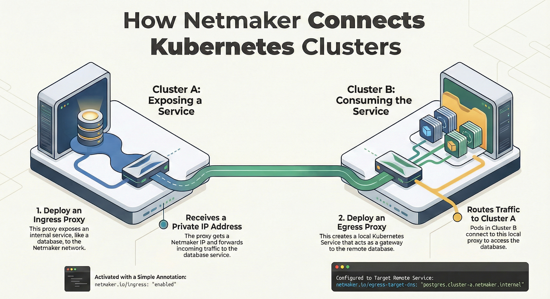
How Netmaker Helps
Netmaker can significantly enhance the management of Layer 2 networks by offering a robust platform for creating and managing virtual overlay networks, which allows for seamless connectivity between devices across multiple locations. One of Netmaker's key features is its ability to create a flat network using WireGuard, enabling fast and secure encrypted tunnels that facilitate efficient data transfer. This can help in managing MAC addresses and data frames by ensuring that all devices, regardless of their location, can communicate as if they are on the same local network. This is particularly useful in environments where managing multiple Layer 2 segments is necessary, as it reduces complexity and enhances security by providing a controlled and encrypted environment for data transmission.
Furthermore, Netmaker's Egress Gateway feature allows for external networks to be reached, simplifying the integration of different network segments and supporting VLAN configurations. This capability can help reduce unnecessary broadcast traffic in a Layer 2 network, thereby improving overall network performance. The tool also supports the use of Remote Access Gateways, which enables secure access for external clients, further enhancing the flexibility and scalability of network management. These features make Netmaker an ideal solution for businesses looking to optimize their Layer 2 network operations and ensure secure, efficient communication across their network infrastructure. Get started with Netmaker here.


.svg)